


High-speed photography refers to the art of taking photographs of high-speed phenomena, typically a popping water-balloon or a bullet breaking an object. The setup is usually a dark room where the camera is set to "bulb," that is, the shutter is open, and the flash is fired at the moment when the balloon is popped or the bullet enters or leaves the object. Firing the flash at the right moment usually involves a sound-activated trigger placed in a position where the delay of the sound propagating from the gunfire matches the bullet's travel distance. When the microphone of the sound-activated trigger picks up noise, the trigger shorts the input of the flash unit and illuminates the subject.
But why move the microphone around when you can easily build a unit with a programmable millisecond delay? And while you're at it, why not have the unit accept a variety of other detectors, such as a broken IR or laser beam, light, etc.? Oh, and maybe have it fire an entire series of flashes with a programmable delay inbetween once it has ignored an initial series of preflashes?
Easy enough. All you need is a PICAXE 08M and a few other components. The PICAXE 08M is a microcontroller that can easily be programmed with free software tools and a USB or serial cable while placed in its target environment. There are Windows and Mac tools available, but I haven't experimented with those. On Linux, all you need is the tool called LinAXEpad and, if you're using the USB cable, an addition to /etc/modules that says:
# Install the PicAXE USB cable support.
ftdi_sio vendor=0x0403 product=0xbd90
This is necessary because although the cable is natively supported by Linux (at least on the current Ubuntu version 10.10), apparently it doesn't report its identity correctly to Linux, which responds by not loading the required module. The above line fixes that problem by forcing the correct module to be loaded when a USB unit with a certain vendor and product ID is detected.
Parts List
For the controller, you'll need the following parts:
- 1 x PICAXE 08M (U1)
- 1 x TSOP1138 SIRC IR receiver (U2)
- 1 x MOC3020 optocoupler (U3)
- 1 x 3-pin jumper (J1)
- 1 x BC547 transistor (Q2)
- 2 x 33 k? resistors (R7, R8)
- 1 x 10 k? resistor (R1)
- 1 x 22 k? resistor (R2)
- 2 x 470 ? resistor (R3, R5)
- 1 x 2,2 k? resistor (R6)
- 1 x flash hotshoe with a wire connector, or a similar connection to your flash unit.
I got my flash hotshoe and connectors from FlashZebra. I wanted a fairly long wire to the hotshoe, so I purchased a PC to flash hotshoe adapter (Item #0065) and a 5 meter PC sync cable (item #0060) and simply cut the wire so it could be soldered to the controller board. (As it turned out, the hotshoe on my flash unit appears to be broken, so I'm using only the sync cable. But that's a different story.)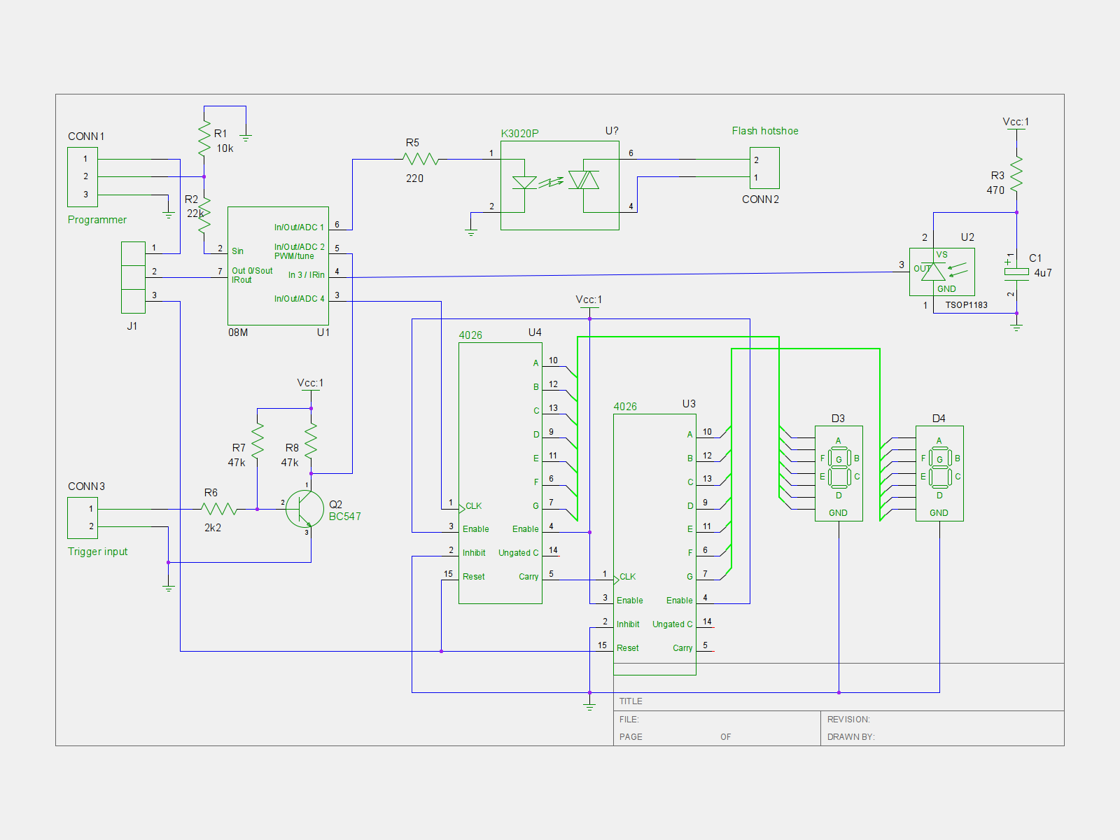 The following optional parts provide a digital display of the millisecond settings which is not required but highly recommended:
- 2 x 4026 decade counters and 7-segment drivers
- 2 x Common cathode 7-segment displays
You may download the schematic here or view it by clicking on the thumbnail to the right. It was developed with gEDA. I suspect gEDA's file format is intended to be compatible with a variety of schematics tools, but I haven't made any attempts opening the schematic with other tools. gEDA is in Ubuntu's repositories and may be installed with the package manager.
Construction
The picture below shows the placement of the components on a regular prototyping board with strips. The "x" markings indicate where the strips should be broken (ten places total):
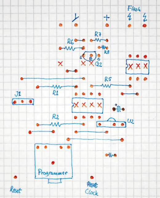 The programmer connector is the one that comes with the PICAXE 08M kits that are available from the store on the PICAXE homepage. You may not need it, but it will make programming the PICAXE easier.
The detector (covered later) is connected to the pin next to the ground symbol that I forgot to label. Detection is indicated by driving this input low, enabling multiple detectors to be connected in parallel if they use open-collector outputs.
If you want the display, place the 4026 ICs on the controller board and the 7-segments on another prototyping board as shown here (click on the picture for a larger version):
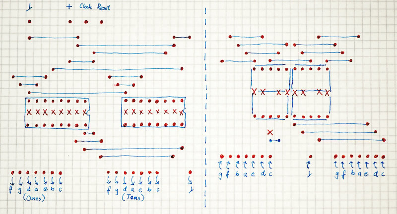 The 'x' marks indicate where the veroboard strips should be cut. Note that the middle strip in the 7-segments should not be cut; also, there's a cut below the tens digit. Clock and Reset are connected to the controller board's Clock and Reset outputs.
Short jumper J1 in the position closest to the PICAXE 08M, and program the PICAXE 08M with the following BASIC program:
' Flash Trigger

' IR detector codes:
'    NN        number of milliseconds to wait
'    CH+ NN    number of flashes to fire
'    CH- NN    delay in tenths of seconds between each flash
'    Power NN  number of trigger intputs (e.g., preflashes) to ignore

#picaxe 08m
#com /dev/ttyUSB0

' Preload the EEPROM with defaults:
' Countdown value: 10.
' Default number of ignores: 0.
' Number of flashes: 1
' Tenth of seconds between flashes: 20.
eeprom 0, ( 10, 0, 1, 20 )


' Pin 0: Reset 4026-based 7-segment counter.
' Pin 1: Output to flash optocoupler.
' Pin 2: Input from trigger circuits - audio detector, IR break, etc.
' Pin 3: IR input.
' Pin 4: Count a 4026-based 7-segment counter.
input 2
output 1, 4
low 1

symbol i = b0
symbol j =  b1
symbol k = b2
symbol two_digits = b4
symbol flash_pause_length = w3 ' b7:b6
symbol ignore_count = b8
symbol countdownvalue = b10
symbol number_of_ignores = b11
symbol number_of_flashes = b9
symbol flash_delay = b12
symbol irreceiverpin = pin3
symbol triggerpin = pin2
' symbol infra = b13 (these are synonymous)

' Restore the settings from EEPROM.
read 0, countdownvalue
read 1, number_of_ignores
read 2, number_of_flashes
read 3, flash_delay
flash_pause_length = flash_delay * 100

' Output the countdown value to the 4026 counters.
two_digits = countdownvalue
gosub showcounter

' If pin 2 becomes low, an interrupt triggers the countdown.
setint %00000100, %00000100 ' interrupt when pin 2 goes high.


main:
	' Wait for a key. Poll in order to allow interrupts.
waitforiractivity:
	if irreceiverpin = 1 then waitforiractivity
	infrain2

	' If it's a digit key, then it's the countdownvalue.
	if infra < 10 then
		' Decode the first key, bypassing wait and validation.
		gosub getonedigit_nowait
		' Get the second digit of the two-digit number.
		gosub getseconddigit
		countdownvalue = two_digits
		' Store the countdown timer value in EEPROM.
		write 0, countdownvalue
	else
		select case infra
		' Power indicates the number of flashes to ignore.
		case 21
			' Show the previous ignore count.
			two_digits = number_of_ignores
			gosub showcounter
			' Get the new value.
			gosub gettwodigits
			number_of_ignores = two_digits
			' Store the value in EEPROM.
			write 1, number_of_ignores
			' Set the ignore counter which is used in the interrupt routine.
			ignore_count = number_of_ignores
		' CH+ indicates the number of flashes to fire.
		case 16
			' Show the previous flash count.
			two_digits = number_of_flashes
			gosub showcounter
			' Get the new value.
			gosub gettwodigits
			number_of_flashes = two_digits
			' Store the value in EEPROM.
			write 2, number_of_flashes
		' CH- indicates the delay in tenths of seconds between each flash.
		case 17
			' Show the previous delay.
			two_digits = flash_delay
			gosub showcounter
			' Get the new value.
			gosub gettwodigits
			flash_delay = two_digits
			flash_pause_length = flash_delay * 100
			' Store the value in EEPROM.
			write 3, flash_delay
		endselect

		' Show the countdown value again after a short delay
		pause 1000
		two_digits = countdownvalue
		gosub showcounter
	endif

	goto main


' Read one digit key from the remote.
getonedigit:
trydigitagain:
	infrain2
	' Keep trying until a valid number key has been entered.
	if infra > 9 then trydigitagain
	' Label used to bypass waiting and validating the digit.
getonedigit_nowait:
	' Keys '1' through '9' have values 0 through 8, and key '0' has value 9.
	' Add one, and perform a modulus 10 to wrap the '0' key around, and we
	' have the true value of the key.
	infra = infra + 1
	infra = infra // 10
	' Wait until the key has probably been released.
	pause 500
	return


' Read two digit keys from the remote and return the two-digit value.
gettwodigits:
	gosub getonedigit
	' Label used to bypass waiting for the first digit.
getseconddigit:
	' Move the first digit to the tens position.
	two_digits = infra * 10
	gosub getonedigit
	' Add the lower digit to the ones position.
	two_digits = two_digits + infra
	' Display the entered value.
	gosub showcounter
	return


' Show the value of "two_digits" by resetting the display and counting
' to the display value.
showcounter:
	' Reset the counters.
	pulsout 0, 1 ' 10 us pulse
	' Count to the display value.
	if two_digits = 0 then endshow
	for i = 1 to two_digits
		pulsout 4, 1 ' 10 us pulse
	next i
endshow:
	return


' On triggering, enter the trigger interrupt.
interrupt:
	' If no more triggers (e.g., preflashes) should be ignored, fire the flash.
	if ignore_count = 0 then
		' Delay the first flash.
		if countdownvalue = 0 then endcountdown
		for j = 1 to countdownvalue
			' The loop itself is sufficient pause.
		next j
endcountdown:
		' Pulse the flash pin number_of_flashes times,
		' waiting pause_length between each flash.
		for j = 1 to number_of_flashes
			pulsout 1, 100 ' 1 ms pulse
			pause flash_pause_length
		next j
		' Reset the ignore count.
		ignore_count = number_of_ignores
	else
		' Count the numbers of triggers to ignore.
		dec ignore_count
	endif

	' Wait until pin 2 goes low before re-enabling interrupt.
waituntilnotrigger:
	if triggerpin = 1 then waituntilnotrigger
	' Re-enable interrupt when pin 2 goes high.
	setint %00000100, %00000100
	return
Now remove the short on jumper J1 and place it in the outermost position instead.
Instructions
Connect your favorite detector to the input on the controller, and connect the flash to the controller's flash output. Power the controller with a 5-Volt supply. Three 1.5 Volt batteries (supplying 4.5 Volts) will suffice.
Use a Sony TV remote control (or any other remote control that uses the Sony IR protocol) to program the controller's delays as follows:
- Enter a two-digit number to set the number of milliseconds the controller should wait before firing the flash after an input is detected.
- Press "Power" followed by a two-digit number to set the number of inputs that should be ignored. This is good for, e.g., slave flashing that shouldn't react to a series of measurement preflashes, or for ignoring the first sounds of some setup that makes noise (such as clicks) prior to the "real" sound.
- Press "CH-" followed by a two-digit number to set the number of flashes that should be fired.
- Press "CH+" followed by a two-digit number to set the delays between the flashes in tens of seconds.
For example, to make the controller wait 35 milliseconds after the fifth input is detected, then fire a series of six flashes with a one second pause between each flash, issue the following commands with the remote: press "35" to set the millisecond delay to 35 milliseconds. Press "CH-" followed by "06" to set the number of flashes. Press "CH+" and "10" to set the delay to ten tenths of a second (that is, one second total). Finally, press "Power" and "04" to tell the controller to ignore the four first detections.
The steps may be performed in any order. Each time you've entered a two-digit number, the number will be displayed if the display board is connected. After about a second, the display will reset to display the delay value. The unit will remember your settings next time it is powered on.
The controller reacts to input when a low pulse is detected on the input. Detector units should simply drive the input low (for example, by using an open-collector output stage) when they detect sound, light, etc. I'll provide some sample detectors later on this blog.
Update February 14, 2011: Tripwire detector.
The nearly complete flash trigger is shown below. It still needs various connectors for the input and the flash unit and shouldn't depend on the power supply visible in the background, but otherwise everything is finished. The IR receiver is hiding right above the display inside the box: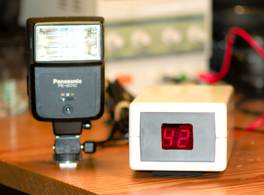
Finally, the unit hasn't been calibrated. The manual states that the BASIC instructions are executed at about one every millisecond, making the for loop take something in that order. It is almost certain that the delay isn't really measured in milliseconds but rather a little less or a little more, but at least "42 milliseconds" will always be the same duration if not 42 milliseconds. The setfreq command together with one or two dummy instructions can probably bring the timing reasonably close to millisecond precision. However, I believe that for the purposes of high-speed photography, it's the constant (and short) delay that is important, not the exact number of milliseconds. Otherwise I'd have had to rely on some external timer circuit for help.

I like photography and i really appreciated this post, thanks for sharing