
Data General Nova 3 printed circuit board, owned by Emil Sarlija. (Photo credit: Wikipedia)
When your printed circuit boards (PCBs) become a little too complicated to draw by hand, or when you realize that schematics and PCB capturing is quite easy using CAD tools such as Eagle, you soon learn that the next challenge is how to transfer the PCB layout to the raw PCB copper board.
There are many tutorials on that on-line, which all boil down to three steps:
- Print the PCB onto paper using a laser printer. You'll have to experiment with various paper types and number of times you need to print on top of the same image in order to get enough ink.
- Push the printed circuit board layout against the PCB while heating it, typically using an iron or a laminator. You'll have to experiment with heat and pressure.
- Somehow peel off the paper without tearing the PCB tracks off. Depending on the type of paper, you'll have to soak it in water for some time, or you'll have to carefully peel off the paper little by little.
Unfortunately, even after many experiments, I've found that the results were less than adequately predictable. I'm not patient enough to go through retries or toasted PCBs. The good thing is that photo printing is so easy it can hardly fail. The major advantage of photo PCBs is repeatability and possibly a higher resolution PCB tracks, although I've heard people talk about being able to produce sub 10 mils PCB tracks using the paper transfer method.
Photo printing involves three steps, too:
- Print the PCB layout onto transparent film. Virtually all laser printers can do that. One print will probably suffice.
- Put the transparent film on top of a photo-prepared PCB (you can buy those) and expose with UV light for about five minutes.
- Develop the PCB.
Developing is much like etching: put the exposed PCB into a chemical solution until the tracks are clear, and that's it. UV exposure is also easy: put an UV lamp over the PCB and turn it on for a couple of minutes, then turn it off. You'll probably want to have it inside of a box to avoid looking at it.
And now that you have the box, you might also want a timer, preferably an electronic one. The following schematic is an example of making an easy digital timer that allow you to set the exposure time from one to nine minutes.
The design revolves around the PICAXE 08M. You may need to alter the code a bit for the newer 08M2, which is faster, so that the timing loop is repeated several more times. The schematic is quite simple (click the image for a larger version):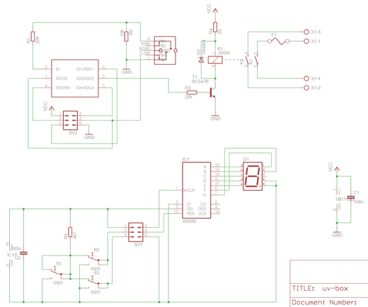 The PICAXE 08M uses two outputs for the display, two inputs for three buttons, and one output for a relay which turns on or off the UV lamps. Otherwise, the PICAXE 08M is connected to a programming socket through a few resistors as suggested in the PICAXE Basics manual.
The three buttons are used to set the timer value: one for incrementing the value, one for decrementing the value, and one for starting the timer. Any of the keys can be used to shut off the lamp prematurely.
The up and down button, S2 and S3, are pulled up, so that a "low" value of the corresponding pin on the PICAXE 08M implies that the particular buttons is pressed. The third button, S1, pulls both buttons to ground, so that it seems as if they're both pressed at the same time. This tells the PICAXE 08M that the "start" button has been pressed.
The timer value is displayed on a 7-segment LED display using just two signals: one signal resets a 4026 counter (which outputs its value in 7-segment format, and is capable of driving a 7-segment display), and another signal counts the 4026 one count up. By resetting and quickly counting, any value from 0 to 9 is displayed with only a slight blink in the display.
The code for the timer is as follows:
' UV Box Exposure Timer

#picaxe 08m
#com /dev/ttyUSB0

' Preload the EEPROM with defaults:
' Value: Last exposure time. Default is 7 minutes.
eeprom 0, ( 7 )


' Pin 0: Reset 4026-based 7-segment counter.
' Pin 1 and pin 3: Button input (00=none, 01='down', 10='down',
'                  11='start'/'stop').
' Pin 2: UV lamp on/off.
' Pin 4: Count a 4026-based 7-segment counter.
input 1, 3
output 0, 2, 4

symbol i = b0
symbol exposuretime = b1
symbol digit = b2
symbol button1 = b3
symbol buttonvalue = b4
symbol minutesleft = b5
symbol minutecounter = w3 ' b6:b7

' Turn off the UV lamp.
low 2

' Restore the settings from EEPROM.
read 0, exposuretime
' Display the exposure time
let digit = exposuretime
gosub showdigit

main:
    ' Wait for the user to push start. Meanwhile, scan for
    ' up and down buttons.
    gosub scanbuttons
    if buttonvalue = 1 then
        gosub countdown
    else if buttonvalue = 2 then
        gosub countup
    else if buttonvalue = 0 then
        ' Write the exposure time to EEPROM.
        write 0, exposuretime
        gosub expose
        ' Restore the display.
        let digit = exposuretime
        gosub showdigit
    endif
    pause 150
    goto main


' Expose PCB.
expose:
    ' Turn on the UV lamp.
    high 2
    ' Wait half a second to give the user time to release
    ' the key.
    pause 500
    let minutesleft = exposuretime + 1
    let digit = exposuretime
exposeminute:
    gosub showdigit
    ' Loop counts in tenths of seconds, and compensate for
    ' some loop overhead.
    let minutecounter = 590
exposeloop:
    ' If the user presses a key, then turn off the lamp and
    ' return to the main loop.
    gosub scanbuttons
    if buttonvalue <> 3 then goto endexposure
    pause 99
    dec minutecounter
    if minutecounter > 0 then goto exposeloop
    ' Count down the number of minutes left.
    dec digit
    dec minutesleft
    if minutesleft > 1 then goto exposeminute
endexposure:
    ' Wait half a second to give the user time to release
    ' the "stop" (start) key.
    low 2
    if buttonvalue = 0 then
        pause 500
    endif
    return


' Scan the buttons to see if one of them is pressed.
' buttonvalue = 0: both pressed,
' buttonvalue = 1: button 2 pressed,
' buttonvalue = 2: button 1 pressed,
' buttonvalue = 3: none pressed.
scanbuttons:
    let buttonvalue = pin1 * 2 + pin3
    return


' Increment the exposure time.
countup:
    inc exposuretime
    if exposuretime < 10 then goto displaynewexposure
' Decrement the exposure time.
countdown:
    dec exposuretime
    if exposuretime < 1 then
        exposuretime = 1
    endif
displaynewexposure:
    digit = exposuretime
    gosub showdigit
    return


' Show the value of "digit" by resetting the display and
' counting to the display value.
showdigit:
    ' Reset the counter.
    pulsout 0, 1 ' 10 us pulse
    ' Count to the display value.
    if digit = 0 then endshow
    for i = 1 to digit
        pulsout 4, 1 ' 10 us pulse
    next i
endshow:
    return
The code should be mostly self-explanatory. Refer to the in-code comments for details.
The PCB is laid out in two parts, as indicated by the schematic; one for the "main board," which includes the processor and the relay, and one for the user interface, which includes the display and the keys, ready to be mounted in a plate: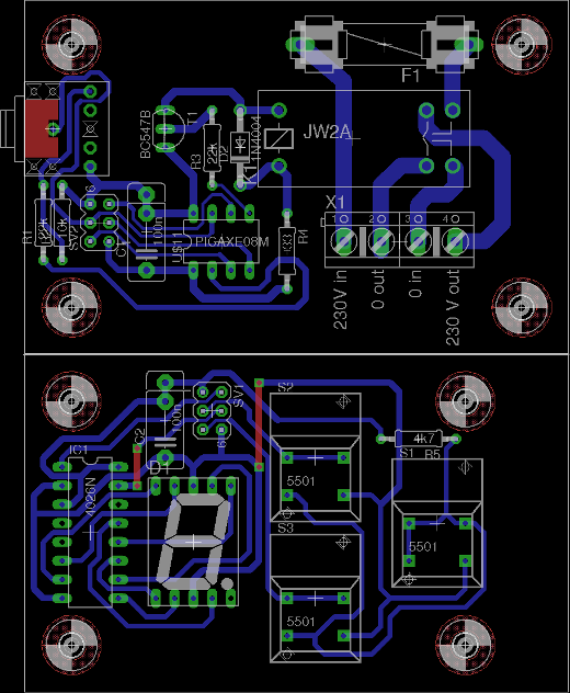 The PCB is single-layer, so the routing is somewhat convoluted. The two "top layer tracks" are easily added as jumpers instead of going through the additional effort of creating a double sided PCB.
I won't get into detail about how I obtained the three UV tubes used in the exposure box and how they're connected, because obtaining the UVB tubes cheaply from a local supplier was a bit of luck, and the tubes are wired like any other tube with ballast and starter. The final version in a wooden box looks like this on a somewhat messy workbench: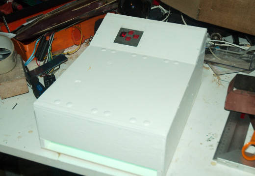 The required exposure time for a photo print is about four to five minutes using this exposure box.