When I was young, it seemed that life was so wonderful,
a miracle, oh it was beautiful, magical.
And all the birds in the trees,
well they'd be singing so
happily, joyfully, playfully watching me.
But then they sent me away to teach me how to be
sensible, logical, responsible, practical.
And they showed me a world where I could be so
dependable, clinical, intellectual, cynical.
(The Logical Song, Supertramp, 1979)
The grandmaster of a martial arts branch once remarked that the head only takes up one eighth of the entire body proper. Anyone that uses only his head to think with is seven-eights paralyzed.
Yet often I hear atheists cry: "rationality!," "logic!," "reason!", etc. when they argue that religious people are separating themselves from the real world. They cling to the intellectual and the abstract. Apparently their real world is restricted to the upper one-eighth of the body.
The last seven-eights of the body does not think in the intellectual sense of the word. However, the body feels and senses. Dr. Antonio Damasio explains in his book, Descartes' Error, that it is not the human brain that controls a human being's rationality. It is instead the body that creates what Damasio named "somatic markers," or bodily points of reference, that direct the brain. Body and brain join in a reciprocal, closed-loop action where the brain is just one of many organs that together spark reason.
Damasio experimented with patients suffering from a brain damage that prevented them from applying their somatic markers. To his surprise, Damasio discovered that these people were just as intelligent as other people, only were these people controlled exclusively by their intelligence, that is, by their brain's reasoning alone. Yet it was as if their goal had changed. Deprived of the use of their somatic markers the actions of the patients showed that the patients unconsciously—but apparently very deliberately—attempted to create problems for themselves, financially as well as socially. Denying their bodily feelings and relying on their reasoning alone the patients had become self-destructive.

We consider logic the foundation of our rationality in our part of the world. However, some people forget that logic is a means, not an ends. And just like tools such as a hammer can strike pointless blows in the air instead of driving nails into wood, logic can be used without applying it to anything tangible, or it can be used outside its proper scope. You may conclude that there is a god or that there is none, both by means of logic. The use of logic can easily lead to surreal conclusions.
Maybe it is because of our ability to consider meaningless issues and draw logical but wrong conclusions that many Western philosophers have become so impressed by their ability to think that they consider it spectacular. These philosophers include Descartes, Berkeley, and, widely used among atheists, Ayn Rand.
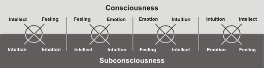
Human beings can draw on many more resources than rationality and logic. The figure below illustrates which psychological and physiological functions we have at our disposal. Beyond the familiar intelligence, which leads to reason and rationality, we also have feeling (bodily sensing), emotion, and intuition. Usually a person is only consciously aware of two of the functions, leaving the other two functions in the person's subconsciousness.
In our part of the world, thinking and intellectualism is well-known, because they serve as basis of scientific method. Thoughts order our impressions whether they are caused by intuition or feeling. Feeling is for the most part socially accepted as valid means of perceiving the world. However, emotion and intuition are considered "chaotic," "inferior," or even "demonic" because they do not fit well into a culture where the body is considered inferior and something to be controlled. Hence it is only intellect and feeling that is considered "normal" in our part of the world. Emotion and intuition are confined to a place in the subconsciousness, where they are usually blamed for deviant behavior.
Atheists may be attracted to rationality and reason, but when they react emotionally to something, often they expose a highly unreasonable identity beneath the surface.
The ability to think clearly, to be rational and logical, can be an incredible strength. But when the ability is out of tune with the other psychological functions, problems arise. To an overly intellectual atheist, rationality becomes a confession of faith where even our very existence is "only an abstraction."
It is quite natural to employ one's dominant functions such as intellectuality and feeling. But as Jung remarked, it is necessary to listen to all of the functions, in particular those functions that are the least developed. It is only then that we realize that there are many situations in life that we cannot effectively appreciate with just the dominant function. One might say that if one faces life with just one function, life is made lesser than life—one kills life.
What we term intelligence today has not always been considered an isolated skill. The term "logic" can be derived from the Greek "logos," which seems to have referred to much more than sheer intellectualism. In some esoteric schools it refers to an inner, divine light that is felt as a warmth rising up through the body, a corporeal feeling that has no direct relation to intelligence. Intelligent logic is often seen as a result of the carnal logic/logos. A person only thinks logically when the logic is shaped by somatic sensation. Logic cannot exist alone, without bodily origin. This is an important point: thoughts will contain no logic unless the logic has first been "felt" by the body; this ancient mysticism is eerily echoed in Damasio's much more recent research.

It is also important to realize that the body cannot learn from intellectual experiences. The use of pressure points in martial arts are a striking example (pun intended). Although it is reasonably easy to explain where pressure points are located by means of diagrams and logic as, for example, Erle Montaigue does it in several of his books, learning to use pressure points in combat is a different matter altogether. No matter how precisely one mentally memorizes the location of a particular pressure point, this knowledge will be useless when an opponent attacks.
However, if you have been shown the location by someone that made you scream from pain, your own knuckles, elbows, fingers, knees or feet will find it without the help of a thinking brain. This "body memory" can only learn from bodily experience.
This kind of learning pervades the esoteric schools, which are sometimes called "oral" schools, because it does not help to read about it. Even if the knowledge was written down, the knowledge would be incomprehensible, because words on paper do not provide carnal experience. One may be able to understand it in an abstract sense, but cannot put it to practical use. Hence, one can write down all of the secrets and pass them on, but in the hands of an uninitiated person the material will be useless. In that sense it is still "secret," because no matter how clearly it is communicated in writing or speech, the "hidden" knowledge is not passed on.
Some things cannot be learned. Either you know them, or you don't. Without having been told, authors such as Tom Kristensen spoke of magic in the shape of a "octopus-like image" in his book, "Havoc," Michael Ende felt the magical influence of people that "distort time" in his book, "Momo," and H. P. Lovecraft used a long array of beings that are well-known in magical visions in other cultures.
Some understanding of the world can only be expressed via the symbolism of intuition, and some understanding requires the empathy of emotion. These "languages" cannot be learned intellectually; if you do not already know on these levels, you will not understand what you are being told. At best you can repeat it to others. In Pythagoras' cult, the mathematikoi were the people that understood his teaching while akousmatikoi referred to those people that would stand on the outside, who could only listen and perhaps repeat what they had heard.
A person that only uses his head and focuses overly on rationality and logic is a partially disabled person. It is a speaking head with no body. It is a person that rejects his body, just as the Christian culture we live in mandates. It is perhaps not surprising that it was Antonio Damasio who in a 1994 essay in Scientific American remarked that perhaps we have culturally "brain damaged" ourselves in much the same sense as had happened to his patients by physical accident or disease.
In the darkest depths of the esoteric schools, you find that if you fight or deny the forces of darkness, they will defend themselves and attack you. In a more practical sense, if you deny your subconsciousness, you will instead become directed by it, usually in a rather unfortunate direction. Perhaps this is what happens to Damasio's patients or our civilization as a whole.
There is much else to life than cold logic. There is an entire world in the subconsciousness the size of the consciously known world. I appreciate this world, which is confined to the darkness of our minds. If one wishes to understand human motivation in a world focused on thinking and sensing, it is in the forbidden realm of emotion and intuition that one must feel at home.

The members of the former rock group Rockbitch had founded a group that focused strongly on the physical aspect of life. However, while Rockbitch represents feeling and is correct in stating that the left-hand path is largely concerned with physical living, obviously it does not imply that other people should live their life as if part of Rockbitch's stage show (neither do the members of Rockbitch as far as I know). To people that have another perception of eros than a strictly literal interpretation, such a life would be an over-focus on sex. And functionally, if you exaggerate sex, you might as well abstain from it, because both directions are unbalanced--they are abstinence from enjoying life. Such people would achieve the opposite of what they wanted.
Similarly, if you focus too much on rationality, you let yourself become its prisoner instead of its user.
So if you find yourself in a position where you argue or even just speculate whether there might be some gods or metaphysical beings, whether a mental image makes sense, whether reality really exists, or if you consider atheism an "attitude towards life," then they are all signs that seven-eights of your life is ignored: there is still an entire body to use and an entire world to play in.
Now watch what you say or they'll be calling you a
radical, liberal, fanatical, criminal.
(The Logical Song, Supertramp, 1979)
 Hence, the solution was simple: any electronics tinkerer worth his salt can whip together a power supply, or in the case of our smoke detector, a dual power supply providing 4.5 Volts (corresponding to three double-A batteries) and 9 Volts. A generic 12 Volt wall wart purchased inexpensively over Ebay, coupled with a 78L09 for 9 Volts, followed by a 78L05 and a diode for 4.3 Volts (which is close enough to 4.5 Volts), a few stabilization capacitors, and that was it: solder the output of the voltage regulators to the battery connectors, and our smoke detector would never ask for another battery. The dual power supply could probably be crammed into a single battery compartment, but I happened to have a two small pieces of PCB that I had saved. I hate to throw stuff away.
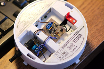
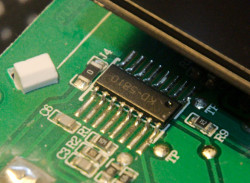 Fortunately, an obscure German discussion revealed that the on-board microcontroller was an otherwise non-descript KD-5810 half-hidden beneath a metal cover, and someone with little electronics experience seemed to have concluded that pin 7 on the processor went high when the detector was triggered. Right indeed; this—and an additional 3.3 V power supply and a voltage divider to safely feed the 9 V signal on pin 7 to the XBee module—was all I needed. The smoke detector now sits happily on the ceiling in our kitchen, and its companions will be mounted as soon as I have constructed power supplies for them as well. It will not be necessary to put Zigbee radios in the remaining smoke detectors, assuming they will are capable of maintaining their native radio contact with each other.
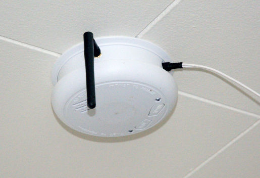 Yes, I know: it is not too pretty yet. The wire should be hidden beneath (well, above) a wire cover, and the antenna should be white. But it works for now.


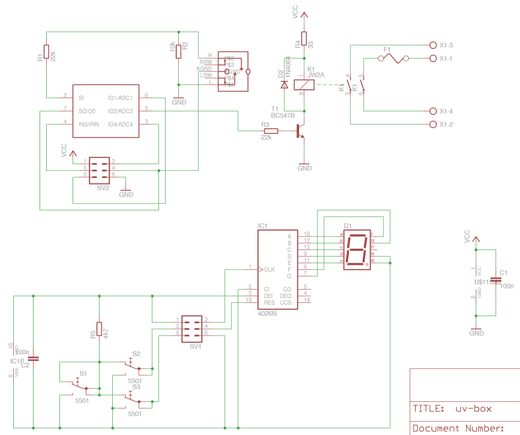
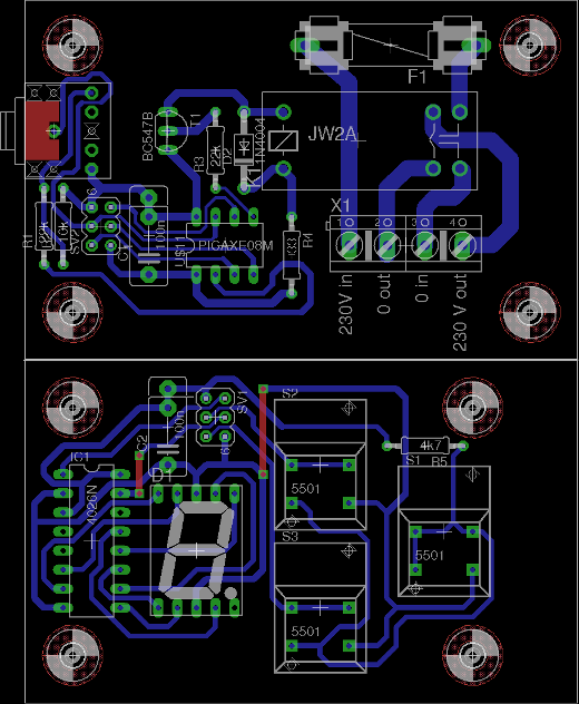
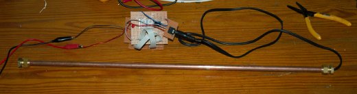
 The required exposure time for a photo print is about four to five minutes using this exposure box.


 But that is neither how I think, nor how I work. Presented with a problem, I see a landscape in front of me with lush valleys, impassable mountains and gorges, walls, streams, highways, buildings, paths, caves, dark forests, and hidden passages. The problem is an area in the distance that is sometimes clearly visible, at other times covered in a hazy mist that obscures the precise location, and sometimes it falls entirely beneath the horizon, giving itself away only by a magnetic attraction that guides the compass needle to point in its direction, or as distant rays revealing where the Sun is setting. It is a map for a Westward chase for the escaping light.
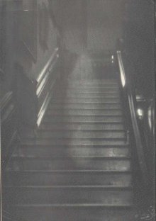 A ghost is a deceased person that haunts the living, because the deceased person has unfinished business or lost property that was highly important to him. In spite of what healthy skepticism might prompt me to believe, I believe in ghosts, because I have seen many of them.
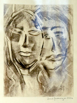
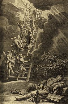 In the mythical universes the axis mundi connects the cosmic planes of existence. In Christianity, the axis mundi is symbolized by the Jacob's ladder, and in the Norse mythology it was Yddgrasil. The the individual, the axis mundi is the connection between sensing and interpretation of the senses, and the connection between his past and his future. It is the person's thread through life.


 Truth is reserved for misguided humans who believe that truth is a goal.
 It is usually considered bad practice to compare groups that you don't like with Nazis. This comparison is made so often, however, that it has earned its own name:
  Nazis of today are unlike the mythical Nazi, because the mythical Nazi never existed. Nazis of today are not necessarily goose-stepping down the Straße, do not necessarily wear armbands, and do not necessarily call themselves Nazis. Only the mythical Nazi does all of this, as well as the few individuals who attempt an ostensive act of the universe of the mythical symbol.
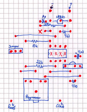 This is a job for the PICaxe 08M, which has built-in support for the Dallas Semiconductors DS18B20 1-wire temperature probe.


 And so "less" is no less.
Recent Comments