


I promised in my millisecond flash timer article that I'd provide a few sample trigger units, so here is the first one. It briefly shorts its output when a connection is broken, serving as input to the millisecond flash timer or the Nikon D70 wired remote hack that I posted earlier this month.
For example, a subject may be fitted with a strip of household aluminum foil which will break when the subject is broken. By connecting each end of the aluminum strip to the input of the "broken-connection flash trigger unit," the unit will send a short low pulse on the output for the timer or the wired remote.
The unit is easily built out of standard components that any electrical hobbyist will have laying around:
- R1, R3, R7: 10 k?
- R2, R6: 2,2 k?
- R5: 470 ?
- C1: 10 µF
- T1, T2, T3, T4: BC547B
Schematic: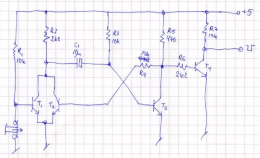 Theory: the unit is based on a monostable multivibrator comprised of R2, R3, R4, R6, C1, T2, and T3. When the tripwire is broken, T1 will open and cause C1 to be discharged. This in turn causes T3 to open until C1 has stabilized. Opening T3 also opens T4, which drives the output low, that is, T4 inverts the signal. The value of C1 causes a pulse of some tenths of a second. This is much longer than needed by the flash trigger unit, but I suspect the D70 wired remote hack might need a somewhat extended pulse, so I'm being plenty on the safe side. A lower value value of C1 will shorten the pulse duration.
Assembly on Veroboard (sorry for the mistakes). Note that the Veroboard strips must be cut below T4, which is also oriented differently than the other three transistors: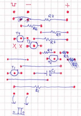 Final tripwire flash trigger unit:
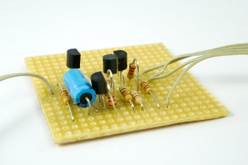 The tripwire input is at the bottom in the Veroboard assembly illustration and on the left in the above photo. Power the unit with 5 volts at - and +, and connect the output (indicated with a low square pulse in the illustration) to the input of the flash trigger unit. Break the tripwire, and the flash is triggered.

Leave a comment