 Der er krav om, at alle husstande skal have postkasser placeret tæt på vejen senest ved udgangen af år 2011. Det gør det muligt for Post Danmark at fyre postbude, fordi de lægger noget af deres hidtidige service ud til borgerne og således sparer tid. Når Post Danmark samtidig fastholder portoen, tjener Post Danmark penge mere på denne bestemmelse.
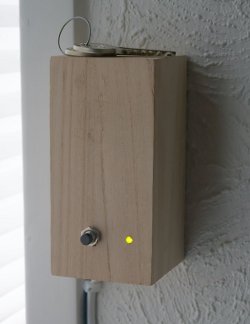
For vores vedkommende betyder det, at vi kommer til at gå forgæves til postkassen nogle gange, men det er der råd for. En gammel reed-kontakt, som jeg havde liggende, gav mig ideen til en simpel, elektronisk konstruktion:
En reed-kontakt er en lille, magnetisk kontakt, som man "trykker" på ved at bevæge en magnet forbi den. Ved at montere en magnet og en reed-kontakt ved postkassens låge, bliver kontakten sluttet, når postkassens låge bliver vippet. Kombiner dette med det simple kredsløb, der er kendt som en bistabil multivibrator, og man har nu de to tilstande, der svarer til, at postkassen er blevet hhv. betjent, og at man har bekræftet tømningen af den. 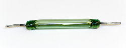 Reed-kontakten trigger den ene tilstand, og en reset-knap trigger den anden tilstand. Kredsløbet og veroboard-placeringen er som følger:
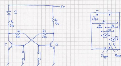
Den endelige konstruktion fylder ikke mere end ca. 2½ x 2 cm. Der tilsluttes 5-6 volt, og en ledning (det er sikkert bedst med en skærmet ledning) med reed-kontakten for enden føres ud til postkassen. Her skal det naturligvis sikres, at tilslultningerne på reed-kontakten er beskyttet mod fugt - brug krympeflex til den slags.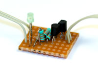 Med en passende placering af reed-kontakten og en magnet ved postkassens låge, bør en bevægelse af lågen give anledning til, at reed-kontakten bliver sluttet. Det får lysdioden til at lyse, indtil en barmhjertig sjæl trykker på reset-knappen. Det bør i denne sammenhæng siges, at jeg ikke har forsøgt mig med praktisk brug endnu og blot konstateret, at konstruktionen med to kontakter virker efter hensigten. Hvis konstruktionen viser sig at være for følsom og trigger uden nogen grund, kan det være nødvendigt at reducere størrelsen af modstandene R2, R3 og R4. Der kan også benyttes andre forsyningsspændinger, men så skal værdien af R1 øges. Ved 9 volt bør R1 være 470 ?.
februar 2011 Archives
Kategorier:
I promised in my millisecond flash timer article that I'd provide a few sample trigger units, so here is the first one. It briefly shorts its output when a connection is broken, serving as input to the millisecond flash timer or the Nikon D70 wired remote hack that I posted earlier this month.
For example, a subject may be fitted with a strip of household aluminum foil which will break when the subject is broken. By connecting each end of the aluminum strip to the input of the "broken-connection flash trigger unit," the unit will send a short low pulse on the output for the timer or the wired remote.
The unit is easily built out of standard components that any electrical hobbyist will have laying around:
- R1, R3, R7: 10 k?
- R2, R6: 2,2 k?
- R5: 470 ?
- C1: 10 µF
- T1, T2, T3, T4: BC547B
Schematic: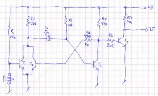 Theory: the unit is based on a monostable multivibrator comprised of R2, R3, R4, R6, C1, T2, and T3. When the tripwire is broken, T1 will open and cause C1 to be discharged. This in turn causes T3 to open until C1 has stabilized. Opening T3 also opens T4, which drives the output low, that is, T4 inverts the signal. The value of C1 causes a pulse of some tenths of a second. This is much longer than needed by the flash trigger unit, but I suspect the D70 wired remote hack might need a somewhat extended pulse, so I'm being plenty on the safe side. A lower value value of C1 will shorten the pulse duration.
Assembly on Veroboard (sorry for the mistakes). Note that the Veroboard strips must be cut below T4, which is also oriented differently than the other three transistors: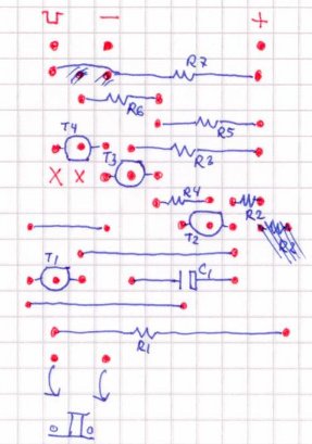 Final tripwire flash trigger unit:
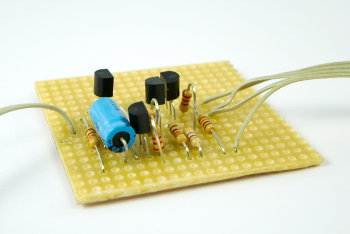 The tripwire input is at the bottom in the Veroboard assembly illustration and on the left in the above photo. Power the unit with 5 volts at - and +, and connect the output (indicated with a low square pulse in the illustration) to the input of the flash trigger unit. Break the tripwire, and the flash is triggered.
Kategorier:
Til rette vedkommende:
Jeg er i løbet af de seneste to uger blevet ringet op tre gange af Telia med henblik på at blive påduttet en telefonforbindelse, som jeg ikke er interesseret i. Første gang gjorde jeg opmærksom på, at jeg er reklamebeskyttet. Anden gang bad jeg Telia notere, at jeg ikke ønsker flere opringninger, fordi dette åbenbart ikke var Telia bekendt.
For et kvarters tid siden blev jeg ringet op tredje gang, hvor en absolut ikke angrende sælger gjorde opmærksom på, at hun ikke vidste, at jeg var reklamebeskyttet, fordi hendes virksomhed benyttede sig af Kraks systemer, og at Krak ikke havde opdateret sin liste over reklamebeskyttede virksomheder.
Til dette vil jeg oplyse overfor Telia, at jeg det er mig fuldstændig uvedkommende hvilke systemer, jeres chikanerende valg af pågående sælgere benytter sig af, og at det ikke er Kraks opgave at opdatere sine systemer med henblik på jeres sælgeres markedsføring af jeres produkter, men derimod den markedsførendes parts opgave. Jeg vil bede jer sørge for, at jeg ikke får yderligere opkald med henblik på salg af Telias produkter til min enkeltmandsvirksomhed.
Hilsen
Ole Wolf
(adresse m.v.)
Kategorier:
High-speed photography refers to the art of taking photographs of high-speed phenomena, typically a popping water-balloon or a bullet breaking an object. The setup is usually a dark room where the camera is set to "bulb," that is, the shutter is open, and the flash is fired at the moment when the balloon is popped or the bullet enters or leaves the object. Firing the flash at the right moment usually involves a sound-activated trigger placed in a position where the delay of the sound propagating from the gunfire matches the bullet's travel distance. When the microphone of the sound-activated trigger picks up noise, the trigger shorts the input of the flash unit and illuminates the subject.
But why move the microphone around when you can easily build a unit with a programmable millisecond delay? And while you're at it, why not have the unit accept a variety of other detectors, such as a broken IR or laser beam, light, etc.? Oh, and maybe have it fire an entire series of flashes with a programmable delay inbetween once it has ignored an initial series of preflashes?
Easy enough. All you need is a PICAXE 08M and a few other components. The PICAXE 08M is a microcontroller that can easily be programmed with free software tools and a USB or serial cable while placed in its target environment. There are Windows and Mac tools available, but I haven't experimented with those. On Linux, all you need is the tool called LinAXEpad and, if you're using the USB cable, an addition to /etc/modules that says:
# Install the PicAXE USB cable support.
ftdi_sio vendor=0x0403 product=0xbd90
This is necessary because although the cable is natively supported by Linux (at least on the current Ubuntu version 10.10), apparently it doesn't report its identity correctly to Linux, which responds by not loading the required module. The above line fixes that problem by forcing the correct module to be loaded when a USB unit with a certain vendor and product ID is detected.
Parts List
For the controller, you'll need the following parts:
- 1 x PICAXE 08M (U1)
- 1 x TSOP1138 SIRC IR receiver (U2)
- 1 x MOC3020 optocoupler (U3)
- 1 x 3-pin jumper (J1)
- 1 x BC547 transistor (Q2)
- 2 x 33 k? resistors (R7, R8)
- 1 x 10 k? resistor (R1)
- 1 x 22 k? resistor (R2)
- 2 x 470 ? resistor (R3, R5)
- 1 x 2,2 k? resistor (R6)
- 1 x flash hotshoe with a wire connector, or a similar connection to your flash unit.
I got my flash hotshoe and connectors from FlashZebra. I wanted a fairly long wire to the hotshoe, so I purchased a PC to flash hotshoe adapter (Item #0065) and a 5 meter PC sync cable (item #0060) and simply cut the wire so it could be soldered to the controller board. (As it turned out, the hotshoe on my flash unit appears to be broken, so I'm using only the sync cable. But that's a different story.)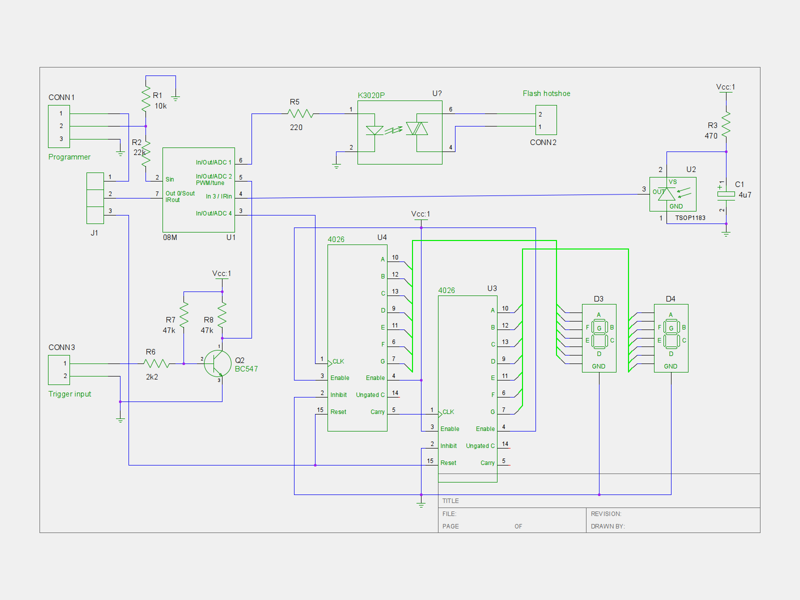 The following optional parts provide a digital display of the millisecond settings which is not required but highly recommended:
- 2 x 4026 decade counters and 7-segment drivers
- 2 x Common cathode 7-segment displays
You may download the schematic here or view it by clicking on the thumbnail to the right. It was developed with gEDA. I suspect gEDA's file format is intended to be compatible with a variety of schematics tools, but I haven't made any attempts opening the schematic with other tools. gEDA is in Ubuntu's repositories and may be installed with the package manager.
Construction
The picture below shows the placement of the components on a regular prototyping board with strips. The "x" markings indicate where the strips should be broken (ten places total):
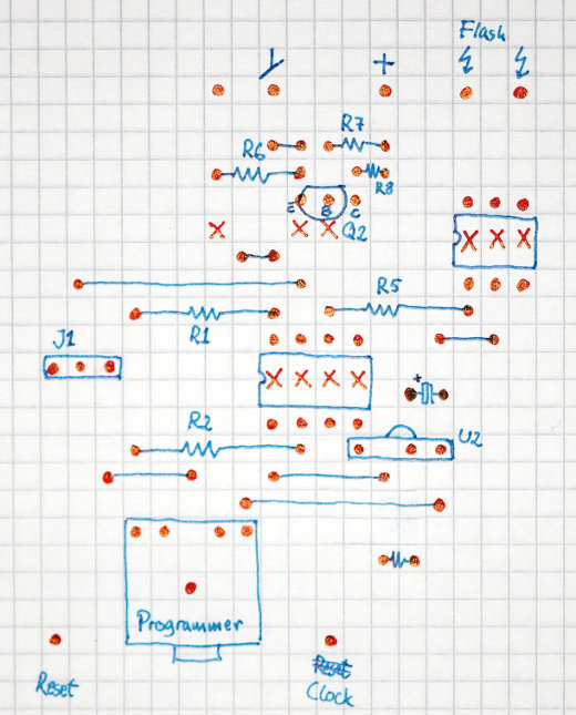 The programmer connector is the one that comes with the PICAXE 08M kits that are available from the store on the PICAXE homepage. You may not need it, but it will make programming the PICAXE easier.
The detector (covered later) is connected to the pin next to the ground symbol that I forgot to label. Detection is indicated by driving this input low, enabling multiple detectors to be connected in parallel if they use open-collector outputs.
If you want the display, place the 4026 ICs on the controller board and the 7-segments on another prototyping board as shown here (click on the picture for a larger version):
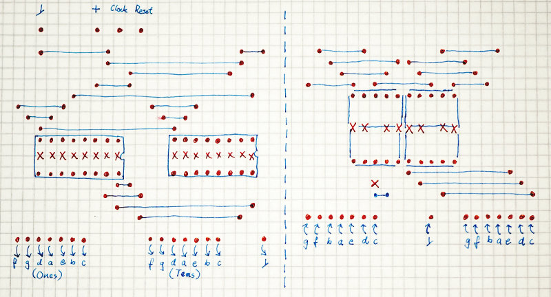 The 'x' marks indicate where the veroboard strips should be cut. Note that the middle strip in the 7-segments should not be cut; also, there's a cut below the tens digit. Clock and Reset are connected to the controller board's Clock and Reset outputs.
Short jumper J1 in the position closest to the PICAXE 08M, and program the PICAXE 08M with the following BASIC program:
' Flash Trigger

' IR detector codes:
'    NN        number of milliseconds to wait
'    CH+ NN    number of flashes to fire
'    CH- NN    delay in tenths of seconds between each flash
'    Power NN  number of trigger intputs (e.g., preflashes) to ignore

#picaxe 08m
#com /dev/ttyUSB0

' Preload the EEPROM with defaults:
' Countdown value: 10.
' Default number of ignores: 0.
' Number of flashes: 1
' Tenth of seconds between flashes: 20.
eeprom 0, ( 10, 0, 1, 20 )


' Pin 0: Reset 4026-based 7-segment counter.
' Pin 1: Output to flash optocoupler.
' Pin 2: Input from trigger circuits - audio detector, IR break, etc.
' Pin 3: IR input.
' Pin 4: Count a 4026-based 7-segment counter.
input 2
output 1, 4
low 1

symbol i = b0
symbol j =  b1
symbol k = b2
symbol two_digits = b4
symbol flash_pause_length = w3 ' b7:b6
symbol ignore_count = b8
symbol countdownvalue = b10
symbol number_of_ignores = b11
symbol number_of_flashes = b9
symbol flash_delay = b12
symbol irreceiverpin = pin3
symbol triggerpin = pin2
' symbol infra = b13 (these are synonymous)

' Restore the settings from EEPROM.
read 0, countdownvalue
read 1, number_of_ignores
read 2, number_of_flashes
read 3, flash_delay
flash_pause_length = flash_delay * 100

' Output the countdown value to the 4026 counters.
two_digits = countdownvalue
gosub showcounter

' If pin 2 becomes low, an interrupt triggers the countdown.
setint %00000100, %00000100 ' interrupt when pin 2 goes high.


main:
	' Wait for a key. Poll in order to allow interrupts.
waitforiractivity:
	if irreceiverpin = 1 then waitforiractivity
	infrain2

	' If it's a digit key, then it's the countdownvalue.
	if infra < 10 then
		' Decode the first key, bypassing wait and validation.
		gosub getonedigit_nowait
		' Get the second digit of the two-digit number.
		gosub getseconddigit
		countdownvalue = two_digits
		' Store the countdown timer value in EEPROM.
		write 0, countdownvalue
	else
		select case infra
		' Power indicates the number of flashes to ignore.
		case 21
			' Show the previous ignore count.
			two_digits = number_of_ignores
			gosub showcounter
			' Get the new value.
			gosub gettwodigits
			number_of_ignores = two_digits
			' Store the value in EEPROM.
			write 1, number_of_ignores
			' Set the ignore counter which is used in the interrupt routine.
			ignore_count = number_of_ignores
		' CH+ indicates the number of flashes to fire.
		case 16
			' Show the previous flash count.
			two_digits = number_of_flashes
			gosub showcounter
			' Get the new value.
			gosub gettwodigits
			number_of_flashes = two_digits
			' Store the value in EEPROM.
			write 2, number_of_flashes
		' CH- indicates the delay in tenths of seconds between each flash.
		case 17
			' Show the previous delay.
			two_digits = flash_delay
			gosub showcounter
			' Get the new value.
			gosub gettwodigits
			flash_delay = two_digits
			flash_pause_length = flash_delay * 100
			' Store the value in EEPROM.
			write 3, flash_delay
		endselect

		' Show the countdown value again after a short delay
		pause 1000
		two_digits = countdownvalue
		gosub showcounter
	endif

	goto main


' Read one digit key from the remote.
getonedigit:
trydigitagain:
	infrain2
	' Keep trying until a valid number key has been entered.
	if infra > 9 then trydigitagain
	' Label used to bypass waiting and validating the digit.
getonedigit_nowait:
	' Keys '1' through '9' have values 0 through 8, and key '0' has value 9.
	' Add one, and perform a modulus 10 to wrap the '0' key around, and we
	' have the true value of the key.
	infra = infra + 1
	infra = infra // 10
	' Wait until the key has probably been released.
	pause 500
	return


' Read two digit keys from the remote and return the two-digit value.
gettwodigits:
	gosub getonedigit
	' Label used to bypass waiting for the first digit.
getseconddigit:
	' Move the first digit to the tens position.
	two_digits = infra * 10
	gosub getonedigit
	' Add the lower digit to the ones position.
	two_digits = two_digits + infra
	' Display the entered value.
	gosub showcounter
	return


' Show the value of "two_digits" by resetting the display and counting
' to the display value.
showcounter:
	' Reset the counters.
	pulsout 0, 1 ' 10 us pulse
	' Count to the display value.
	if two_digits = 0 then endshow
	for i = 1 to two_digits
		pulsout 4, 1 ' 10 us pulse
	next i
endshow:
	return


' On triggering, enter the trigger interrupt.
interrupt:
	' If no more triggers (e.g., preflashes) should be ignored, fire the flash.
	if ignore_count = 0 then
		' Delay the first flash.
		if countdownvalue = 0 then endcountdown
		for j = 1 to countdownvalue
			' The loop itself is sufficient pause.
		next j
endcountdown:
		' Pulse the flash pin number_of_flashes times,
		' waiting pause_length between each flash.
		for j = 1 to number_of_flashes
			pulsout 1, 100 ' 1 ms pulse
			pause flash_pause_length
		next j
		' Reset the ignore count.
		ignore_count = number_of_ignores
	else
		' Count the numbers of triggers to ignore.
		dec ignore_count
	endif

	' Wait until pin 2 goes low before re-enabling interrupt.
waituntilnotrigger:
	if triggerpin = 1 then waituntilnotrigger
	' Re-enable interrupt when pin 2 goes high.
	setint %00000100, %00000100
	return
Now remove the short on jumper J1 and place it in the outermost position instead.
Instructions
Connect your favorite detector to the input on the controller, and connect the flash to the controller's flash output. Power the controller with a 5-Volt supply. Three 1.5 Volt batteries (supplying 4.5 Volts) will suffice.
Use a Sony TV remote control (or any other remote control that uses the Sony IR protocol) to program the controller's delays as follows:
- Enter a two-digit number to set the number of milliseconds the controller should wait before firing the flash after an input is detected.
- Press "Power" followed by a two-digit number to set the number of inputs that should be ignored. This is good for, e.g., slave flashing that shouldn't react to a series of measurement preflashes, or for ignoring the first sounds of some setup that makes noise (such as clicks) prior to the "real" sound.
- Press "CH-" followed by a two-digit number to set the number of flashes that should be fired.
- Press "CH+" followed by a two-digit number to set the delays between the flashes in tens of seconds.
For example, to make the controller wait 35 milliseconds after the fifth input is detected, then fire a series of six flashes with a one second pause between each flash, issue the following commands with the remote: press "35" to set the millisecond delay to 35 milliseconds. Press "CH-" followed by "06" to set the number of flashes. Press "CH+" and "10" to set the delay to ten tenths of a second (that is, one second total). Finally, press "Power" and "04" to tell the controller to ignore the four first detections.
The steps may be performed in any order. Each time you've entered a two-digit number, the number will be displayed if the display board is connected. After about a second, the display will reset to display the delay value. The unit will remember your settings next time it is powered on.
The controller reacts to input when a low pulse is detected on the input. Detector units should simply drive the input low (for example, by using an open-collector output stage) when they detect sound, light, etc. I'll provide some sample detectors later on this blog.
Update February 14, 2011: Tripwire detector.
The nearly complete flash trigger is shown below. It still needs various connectors for the input and the flash unit and shouldn't depend on the power supply visible in the background, but otherwise everything is finished. The IR receiver is hiding right above the display inside the box: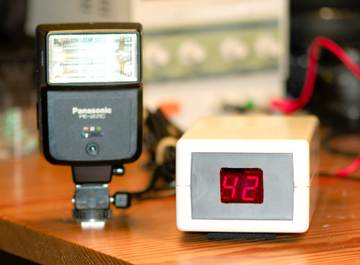
Finally, the unit hasn't been calibrated. The manual states that the BASIC instructions are executed at about one every millisecond, making the for loop take something in that order. It is almost certain that the delay isn't really measured in milliseconds but rather a little less or a little more, but at least "42 milliseconds" will always be the same duration if not 42 milliseconds. The setfreq command together with one or two dummy instructions can probably bring the timing reasonably close to millisecond precision. However, I believe that for the purposes of high-speed photography, it's the constant (and short) delay that is important, not the exact number of milliseconds. Otherwise I'd have had to rely on some external timer circuit for help.
Kategorier:
Kære Post Danmark,
Jeg skriver til jer, fordi jeg undrer mig over kvaliteten af jeres "Track & Trace"-system.
Allerede i slutningen af 1990'erne kunne udenlandske pakkeservices typisk demonstrere "track & trace"-systemer, hvor pakken kunne følges i meget fine detaljer: Modtaget, på vej til sortering, ventende på postcenteret, afgået til transport til andet postcenter, under transport til andet postcenter, modtaget på andet postcenter, under udbringning, m.v.
Min erfaring med Post Danmarks "track & trace" er, at mine pakkers tilstand kun har tre tilstande: Ukendt, ankommet til Taulov, eller afleveret til mig - dvs. uden nogen form for oplysninger, som jeg reelt kan bruge til noget.
I dag venter jeg på en pakke, som jeg modtog "track & trace"-nummeret på fra afsenderen via email den 4. feb. 2011 kl. 11.49. Fredag aften var pakkens status endnu ukendt i følge Post Danmarks "track & trace", og først lørdag morgen fremgik det, at pakken var ved Taulov.
Det er den tilsyneladende stadig, hvis man skal tro jeres "track & trace"-service. Vedhæftede billede viser en forespørgsel d. 7. feb. 2011 kl. 9.09. Jeg er opmærksom på, at der har været week-end, men jeg formoder dog, at der arbejdes mandag morgen, og at pakken status derfor allerede nu som mindstemål bør være kendt, og således kunne følges på "track & trace": Er den f.eks. forsinket (dvs. endnu ikke blevet behandlet)? Er den under transport til Aalborg/Nørresundby, hvor jeg bor? Er den ankomstsorteret i Nørresundby til udbringning formiddag eller eftermiddag?
Disse spørgsmål burde nemt kunne besvares i et IT-system, ikke mindst i betragtning af, at såvel udenlandske som konkurrerende danske pakkeservicevirksomheder har kunnet dette i over 10 år.
Jeg kunne derfor godt tænke mig at høre, hvornår (eller om) Post Danmark har planlagt at rulle næste version af sin "track & trace"-service ud, så vi kunder har mulighed for at trække brugbar information ud af systemet.
Med venlig hilsen, og på forhånd tak,
Ole Wolf
(adresse osv.)
Kategorier:
Det rammer naturligvis umiddelbart de indvandrere, der må gøre det samme arbejde som øvrige danskere til en lavere løn, og en anklage om racisme eller en form for apartheid ligger lige til højrebenet. Men forslaget rammer langt bredere end indvandrerne alene. For når en gruppe mennesker pludselig kan ansættes til en lavere løn end alle vi andre, så bliver det langt sværere for i andre at blive ansat. Vi vil være nødt til at gå ned i løn. Det er sandsynligvis dét, der motiverer Claus Hjort Frederiksen, og den eventuelle racistiske undertone er formodentlig blot en (for ham) behagelig bieffekt.
Det viser, hvad regeringen mener, når den benytter udtrykket "det skal kunne betale sig at arbejde". Deres fokus ligger alene på erhvervslivets interesser, og sætningen henvender sig overhovedet ikke til den arbejdende stand. Når Venstre siger, at det skal kunne betale sig at arbejde, så tænker de på, hvad der kan betale sig for erhvervslivet. Alle vi andre kommer til at tabe på det.
Kategorier:
The Dallas 1-wire protocol makes it possible to attach a variety of devices ranging from counters, temperature sensors, memory, and humidity sensors, onto just a single data wire. Several of the sensors require no supply voltage line; instead, they draw the supply voltage from the data wire in so-called "parasitic" mode. The communication protocol allows a short burst of current on the data line that charges an internal capacitor in each of the attached 1-wire devices. Once charged, the internal capacitors provide just enough current to allow the 1-wire devices to do their thing and respond on the data wire.
A 1-wire controller is necessary, and while it is relatively easy to build a serial version with only a few components, Hobby Boards sells a USB adapter that is compatible with Ubuntu Linux.
Each device has a unique ID that is queried by the controller. Only those devices whose ID matches the controller's request are allowed to respond on the data line. Hence, all 1-wire devices are simply attached in parallel on the data wire, limiting the total wire count to two wires (one for data, one for ground). Some 1-wire devices that require large amounts of currents, such as LCD devices, require their own supply voltage, however. This may increase the wire count to three if you want to power all of these devices from a shared power supply, but you may also choose to power the 1-wire devices separately. The temperature sensors don't require a power supply unless you're using poor wire types, long wires, or have attached a large number of sensors on the same wire.
With Ubuntu, temperature logging requires only one Dallas one 1-wire controller, as many 1-wire temperature sensors as you want, and some scripting skills. Hobby Boards sells 1-wire sensors, too, which readily fit into their USB adapter. However, I chose to purchase a handful of bare DS18B20 temperature sensors from a local electronics outlet instead. I also needed an RJ45 connector for the USB adapter, which appears to be Hobby Boards' preferred connector. I was a little surprised to learn that Hobby Boards had chosen the black wire for data and red one for data/power.
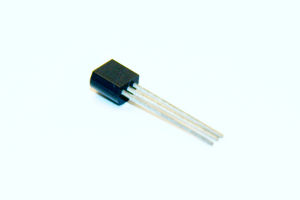 The 18B20 device comes in a TO92 housing. The outermost pins are ground and power supply. When shorted, they indicate parasitic mode where the 18B20 draws power from the data pin in the middle. So, from the USB adapter, ground goes to the outer pins on the 18B20, and data goes to the middle pin. Of course, I built the 18B20 devices into small cases with adapters on them, enabling them to easily be connected in parallel with other cases containing 18B20 devices. For outdoor use, I enclosed the device and the cables in an epoxy-filled case to shield it from moisture.
Next, the software. The Ubuntu Linux kernel already includes 1-wire support, and the only required external software was "digitemp," which is found in the Ubuntu software repositories. I originally installed it on Ubuntu 9.10 where I had to blacklist the DS2940 kernel module. A file named "/etc/modprobe.d/blacklist-ds2940.conf" with the following contents takes care of that:
# To get digitemp to work
blacklist ds2940
It may not be required on current Ubuntu releases, but it probably doesn't hurt.
Plug in the USB adapter, and Ubuntu loads the proper kernel; you can see in /var/log/messages what happens when the adapter is plugged in.
The next step is to determine the unique IDs of the attached 18B20 sensors. Digitemp can be used to send a broadcast query that returns the IDs as follows:
digitemp_ds2940 -w -sUSB
You may need to "sudo" the command. For some reason, this currently doesn't output anything on my own server, but back when I originally queried the IDs, it yielded an output similar to the following:
# digitemp_DS2490 -w
DigiTemp v3.5.0 Copyright 1996-2007 by Brian C. Lane
GNU Public License v2.0 - http://www.digitemp.com
Found DS2490 device #1 at 003/005
Turning off all DS2409 Couplers
...
Devices on the Main LAN
28913B56020000F2 : DS18B20 Temperature Sensor
282221560200006D : DS18B20 Temperature Sensor
(etc.)
You'll have to figure out on your own which device ID (the string to the left in the list that is output) belongs to which sensor. These IDs are required to query the proper device, and must be copied to a configuration file. I called my configuration file "/root/digitemp.conf", and it contains the following:
READ_TIME 2000
LOG_TYPE 1
LOG_FORMAT "%Y-%m-%d %H:%M:%S Sensor %s C: %.2C F: %.2F"
CNT_FORMAT "%Y-%m-%d %H:%M:%S Sensor %s #%n %C"
HUM_FORMAT "%Y-%m-%d %H:%M:%S Sensor %s C: %.2C F: %.2F H: %h%%"
SENSORS 5
# Server Room
ROM 0 0x28 0x91 0x3B 0x56 0x02 0x00 0x00 0xF2
# Home Office
ROM 1 0x28 0xFC 0x63 0x56 0x02 0x00 0x00 0xD0
# Heater
ROM 2 0x28 0x22 0x21 0x56 0x02 0x00 0x00 0x6D
# Outside, East
ROM 3 0x28 0x5E 0x17 0x56 0x02 0x00 0x00 0x90
# Living room
ROM 4 0x28 0x1F 0x3A 0x56 0x02 0x00 0x00 0xC6
The ROM codes are your choice of device numbers and the IDs that were output by the previous broadcast query.
Finally, the script that queries the temperatures of the 1-wire sensors is a simple Bash script stored in the /root folder:
#!/bin/bash

DIGITEMP_CMD=/usr/bin/digitemp_DS2490
CONFFILE=/root/digitemp.conf
STATEFILE=/var/lib/temperature/current
TMPFILE=/tmp/digitemp.XXX

# Abort after first script error.
set -e

# Get a unique temporary tamper-proof file name.
tmp=$(mktemp $TMPFILE)

# Create a full poll list of the temperature array. This takes up to
# 5 seconds per sensor, and therefore must be done to a (slowly growing)
# temporary file.
$DIGITEMP_CMD -q -c $CONFFILE -a -sUSB -l $tmp

# 'Atomically' move the freshly created state file in place.
chmod 644 $tmp
mv $tmp $STATEFILE
# Insert new measurements into database.
/usr/bin/php /root/digitemp-insert.php
Before calling the script, create a writeable directory in /var/lib/temperature, where the sensor outputs are stored in a file named "current". Call the script every, say, five minutes using a crontab entry:
# Read temperature probes every 5 minutes.
*/5 * * * * /root/digitemp.sh > /dev/null 2>&1
The last line in the script calls another script that inserts the temperatures and time stamps for all temperature sensors into a MySQL database. If you don't need logging but only want the most recent temperature output, simply delete the last line of the script and read the current temperatures from /var/lib/temperature/current. You won't need any of the following either in that case.
The MySQL database insertion script simply reads and parses the file in /var/lib/temperature/current and inserts the values into a previously created MySQL database. The database contains the following tables:
- id (int, autoincrement, primary key)
- sensor (tinyint)
- date (datetime)
- temperature (float)
You'll have to create the MySQL database yourself, for example via phpMyAdmin. Remember to assign a user and a password, too.
The MySQL logging script looks like this, except that my password has been obscured:
<?

// Read the temperature log.
$entries = array( );
$fileHandle = fopen( "/var/lib/temperature/current", "r" );
while( ! feof( $fileHandle ) )
{
    $temperatureLogEntry = fgets( $fileHandle );
    // Break down the string, which looks like this:
    // Jul 20 11:25:21 Sensor 0 C: 24.31 F: 75.76
    $entry   = array( );
    $pattern  = '/';
    // Date and time
    $pattern .= "^([0-9]{4}-[0-9]{2}-[0-9]{2} [0-9]{2}:[0-9]{2}:[0-9]{2})";
    // Sensor number.
    $pattern .= " Sensor ([0-9]{1,3}) ";
    // Sensor temperature.
    $pattern .= "C: (-*[0-9]{1,3}\.[0-9]{1,3}) ";
    $pattern .= "/";
    if( preg_match( $pattern, $temperatureLogEntry, $entry ) )
    {
        $entries[ ] = $entry;
    }
}

fclose( $fileHandle );


$mysqlBase = "temperatur";
$mysqlUser = "temperatur";
$mysqlPass = "*************";

$con = mysql_connect( "localhost", "$mysqlUser", "$mysqlPass" );
if( ! $con )
{
    die( 'Could not connect: ' . mysql_error( ) );
}
mysql_select_db( "$mysqlBase", $con );

foreach( $entries as $entry )
{
    $date        = $entry[ 1 ];
    $sensor      = $entry[ 2 ];
    $temperature = $entry[ 3 ];
    $sensorName  = $sensors[ $sensor ];

    $timestamp = strtotime( $date );
    $query = "INSERT INTO temperatur ( sensor, date, temperature ) "
           . "VALUES( '$sensor', '$date', '$temperature' )";
    $result = mysql_query( $query );
}

mysql_close( $con );

?>
To display the temperature log, a web server comes in handy. There are several graphical plotting options available, and I settled for the free version of JpGraph. I downloaded it from the web site because the version in the Ubuntu repositories seemed rather outdated. I recall I had to specify the directory for TrueType fonts and ensure that JpGraph was in PHP's search path, but otherwise I think it worked straight out of the box.
The script that uses JpGraph is called via the "img" HTTP tag. The script compiles image that is embedded into the main graph display script. My graphing script allows the user to enter a plot interval, and is simply the index file, "index.php". Rather than including the PHP scripts here, you may download them as a tarball here: temperature.tar.gz. Install them in a directory together with JpGraph. You'll have to do a few customizations: JpGraph may have to be tweaked a little to make sure it's visible from the scripts; you'll also have to set the database, username, and password in "config.php" according to the MySQL database you created previously; and, you'll want to modify the script to display those sensors that are appropriate for your own setup. Once configured, the script should display an output similar to the following: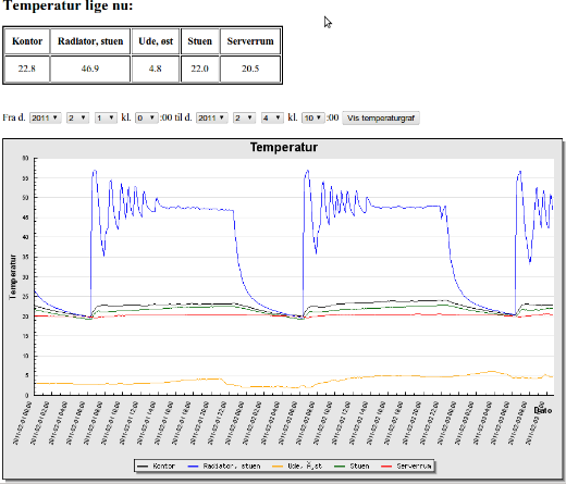
Kategorier:
I'm generally very happy with my Nikon D70, but the remote control bugs me. The D70 will only accept an IR wireless remote, and the sensor is on the front of the camera. This means you can't control the camera remotely from behind the camera, and worse: you can't hook the camera to electronic controllers that take automated pictures.
This may be remedied by hacking the remote control. It involves hacking a device with surface-mounted components, and that requires a steady hand and some soldering experience, not to mention a soldering iron with a pointed tip.
Note: what follows is a hack on the Yongnuo ML-L3 replacement remote controller. I suspect a similar approach is possible with the original Nikon ML-L3, but the connector should probably be soldered to different pins on the Nikon remote.
I didn't want to ruin my original Nikon ML-L3 remote control, so instead I purchased a few replacements from Yongnuo that cost only a fraction of Nikon's original remote: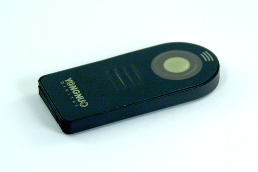 The first step was to open the remote control. The pushbutton front is a thin sheet of metal glued to the circuit board which had to be removed. A hobby knife was all that was required for this operation:
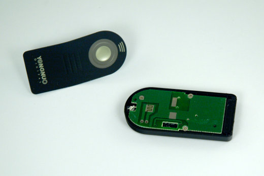 This revealed the pushbutton connectors, and while two thin wires could probably be connected to the two predrilled pads, I went for a different solution where I could add a small connector inside of the remote control. First, I removed the three screws holding the circuit board:
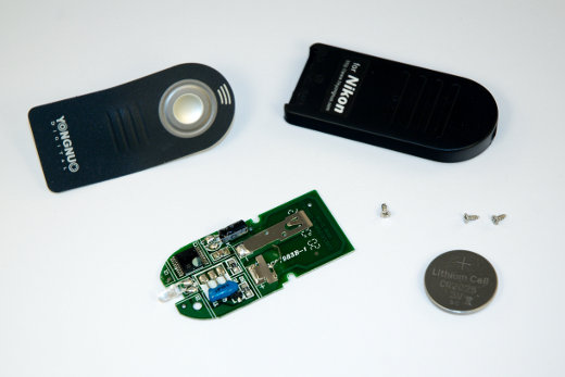 Inspections of the circuit board and measurements with an Ohm-meter revealed that pressing the pushbutton shorts pins 14 and 15 on the integrated circuit found in the upper left corner of the circuit board in the above picture. The next step was to cut a hole for a small connector made out of a straight one-row female header:
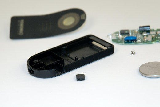 So far, nothing difficult. The next step required careful soldering of two wires to pins 14 and 15 on the surface-mounted integrated circuit. It helped to superglue the connector on top of the circuit first, since this was where it was going to be fastened anyway:
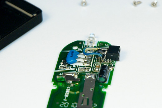 That was it. All that remained was to reassemble the remote control. It turned out the connector was slightly too big for the case so the metal front doesn't quite fit, but I can live with that. It's a learning experience:
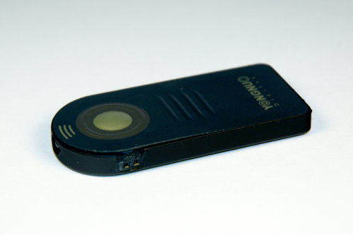
The original pushbutton on the remote still works, and the D70 can now be released by pushing a button that is wired to the connector on the remote control. Of course, the remote control still needs to be placed in front of the camera, but Gaffa is always your friend.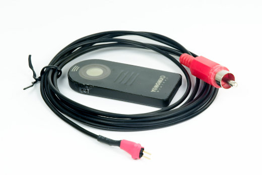
Kategorier: